
Description
Management System with Charge Monitoring and Fire Protection for EEE Final Year Project
- Introduction: Management System with Charge Monitoring and Fire Protection
- Why Choose This Project for EEE Final Year?
- Components of the Project
- Features of the Management System
- Working of the Project
- Step-by-Step Implementation Guide
- Benefits of Charge Monitoring and Fire Protection
- Conclusion
- FAQs
Introduction: Management System with Charge Monitoring and Fire Protection
A Management System with Charge Monitoring and Fire Protection is an ideal demo project for Electrical and Electronics Engineering (EEE) final year students. This project integrates safety measures such as fire detection, charge level monitoring, and automated cooling systems using an Arduino UNO microcontroller.
This solution demonstrates practical implementation of Battery Management Systems (BMS) with real-world applications, ensuring efficient energy management and enhanced safety.
Why Choose This Project for EEE Final Year?
This project stands out for:
- Addressing safety concerns in electrical systems.
- Utilizing real-world components like sensors and relay modules.
- Integrating charge monitoring and fire protection mechanisms.
- Providing hands-on experience with Arduino programming.
A Management System with Charge Monitoring and Fire Protection enhances understanding of renewable energy storage, fire detection systems, and automation.
Components of the Project
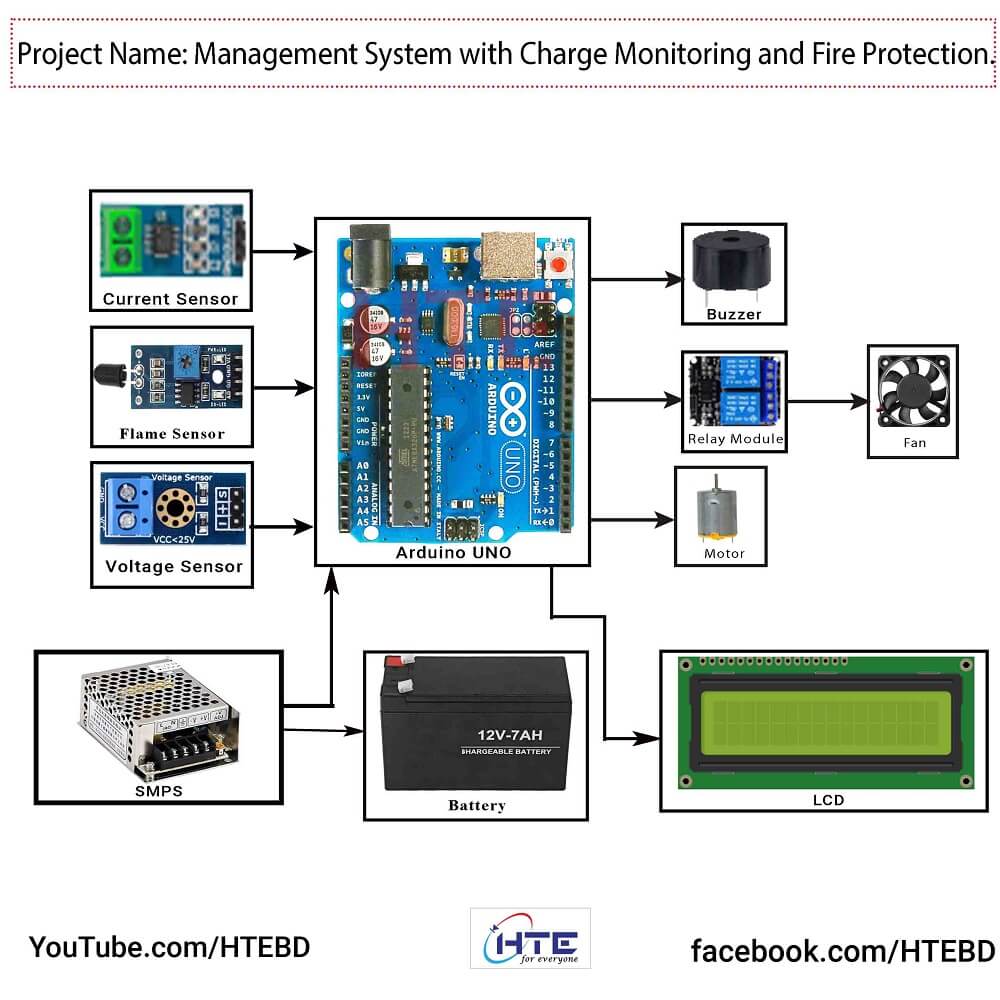
Below are the essential components used to build the Management System with Charge Monitoring and Fire Protection:
- Arduino UNO – The microcontroller for system control.
- Current Sensor – Monitors current flowing through the battery.
- Voltage Sensor – Measures battery voltage levels.
- Flame Sensor – Detects fire hazards.
- NTC Thermistor – Monitors temperature changes for fire safety.
- Relay Module – Controls devices like fans or motors.
- Cooling Fan – Ensures temperature regulation.
- Buzzer – Provides alert signals during fire detection.
- LCD Display – Displays voltage, current, and system status.
- 18650 Batteries – Rechargeable batteries for power storage.
- Battery Management System (BMS) – Manages charge/discharge.
- SMPS (Switched-Mode Power Supply) – Converts AC to DC for input power.
Features of the Management System
The Management System with Charge Monitoring and Fire Protection offers the following features:
H2: Real-Time Charge Monitoring
- Continuous monitoring of battery voltage and current levels.
- LCD display shows real-time values.
H2: Fire Detection and Protection
- Flame sensor and thermistor monitor potential fire hazards.
- Immediate alerts via buzzer and activation of cooling systems.
H3: Automated Cooling System
- Relay-controlled fan activates when temperature crosses a threshold.
H3: Safety and Efficiency
- BMS ensures battery protection against overcharge or over-discharge.
- Enhances battery life and operational efficiency.
Working of the Project
The Management System with Charge Monitoring and Fire Protection operates as follows:
- Charge Monitoring:
- Voltage and current sensors monitor battery parameters.
- Data is displayed on the LCD for real-time status.
- Fire Detection:
- The flame sensor detects fire while the thermistor monitors temperature.
- When fire or abnormal heat is detected, the system triggers a buzzer alert.
- Cooling Activation:
- Relay activates the fan to reduce the temperature of the batteries.
- Protection:
- The Battery Management System (BMS) ensures safe charge and discharge cycles.
Step-by-Step Implementation Guide
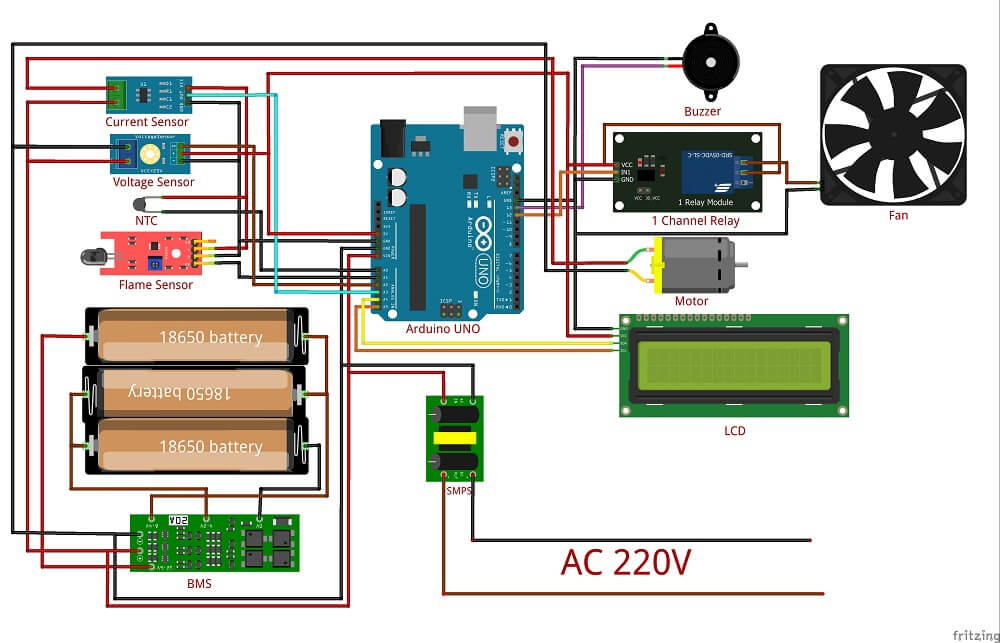
- Assemble Components:
- Connect the current sensor, voltage sensor, flame sensor, thermistor, relay module, buzzer, and LCD to the Arduino UNO.
- Write and Upload Arduino Code:
- Program the Arduino to monitor inputs and trigger outputs based on thresholds.
- Power Connection:
- Connect the 18650 batteries and SMPS for power input.
- Testing and Debugging:
- Verify all sensors, relay, and buzzer functions.
- Simulate fire conditions to test alerts and cooling mechanisms.
- Display Outputs:
- Use the LCD to display charge levels, temperature, and fire alerts.
Benefits of Charge Monitoring and Fire Protection
- Enhanced Battery Safety: Prevents battery failures and potential hazards.
- Real-Time Monitoring: Continuous data on battery parameters.
- Practical Learning: Combines electrical safety, sensors, and automation.
- Cost-Effective: Uses affordable components for a complete safety solution.
Conclusion
A Management System with Charge Monitoring and Fire Protection is a robust and practical project for final year EEE students. It not only ensures battery safety but also showcases real-world implementation of monitoring systems and fire protection mechanisms. By integrating sensors, relays, and the Arduino UNO, students can create a highly efficient and reliable system for charge management and safety.
FAQs
1. What is the purpose of the BMS in this project?
The Battery Management System ensures safe charging, overcharge prevention, and discharge monitoring.
2. Can this project be expanded further?
Yes, it can include IoT integration for remote monitoring.
3. What role does the Arduino UNO play?
Arduino UNO acts as the central controller, processing sensor inputs and activating outputs like relays and buzzers.
Reviews
There are no reviews yet.